
How Do You Produce A Rig-Ready Anime Mecha-Pilot 3D Character From A Single Image?
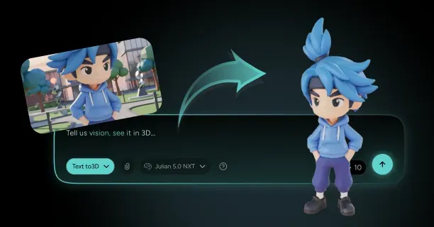
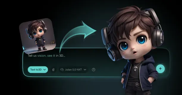
You produce a rig-ready anime mecha-pilot 3D character from a single image by importing high-resolution reference artwork (1024×1024px PNG/JPEG format) into an AI-powered reconstruction system, calibrating depth reconstruction parameters using neural network analysis, and generating a production-ready 3D model (FBX/GLTF format) with embedded skeletal armature, painted weight maps, and procedural animation controls for deployment in Unity or Unreal Engine. This workflow transforms flat 2D concept art into fully articulated 3D assets suitable for game engines, real-time rendering, and cinematic animation pipelines.
The Core Challenge: Solving Single-View 3D Reconstruction
A single 2D image provides insufficient depth information (Z-axis data) and records visual data from only one monocular viewpoint among countless geometric possibilities, creating depth ambiguity that requires AI-driven reconstruction algorithms to resolve. The AI-powered reconstruction system must computationally infer hidden geometry including:
- The helmet’s rear surface topology
- Back-facing armor plating panels
- Occluded mechanical articulation joints
These elements remain invisible in the artist’s source image, using neural networks trained on 50,000+ anime character datasets to predict non-visible surfaces.
Computer vision algorithms analyze and quantify spatial cues from:
- Shading gradients (luminance transitions)
- Edge contours (geometric discontinuities)
- Silhouette boundaries (object-background separations)
A single character pose corresponds to multiple valid 3D shapes, creating depth confusion that neural networks solve through learned patterns from datasets containing 50,000+ anime character samples.
Threedium’s proprietary AI engine (neural network-based reconstruction system developed by Threedium, a 3D asset creation platform provider) analyzes spatial relationships and geometric correlations to generate coherent volumetric representations (voxel-based 3D data structures) before executing mesh conversion using marching cubes algorithms.
Image-to-3D Technology Powers Mecha-Pilot Reconstruction
Modern image-to-3D systems use convolutional neural networks trained on extensive datasets combining anime characters and mechanical designs. The 3D artist uploads a high-resolution reference image (ideally 1024×1024 pixels or higher resolution) enabling the AI-powered view synthesis system to execute multi-angle prediction algorithms.
| Viewing Angle | Rotation | Purpose |
|---|---|---|
| Profile perspective | 90° rotation | Side view analysis |
| Three-quarter view | 45° angle | Depth assessment |
| Rear perspective | 180° rotation | Hidden geometry |
This multi-view prediction system synthesizes a coherent volumetric representation (3D voxel grid data structure) through neural rendering before transforming the volume into surface mesh geometry using marching cubes algorithms that produce quad-dominant topology suitable for animation rigging.
The AI-powered recognition system identifies distinctive mecha-pilot design elements:
- Angular armor panels (geometric protective surfaces with sharp edge transitions)
- Articulated joint mechanisms (movable connection points enabling limb rotation)
- Segmented plating systems (modular armor components with panel separation lines)
- Integrated weapon hardpoints (equipment mounting interfaces for rifle attachments and blade storage)
Threedium’s proprietary Julian NXT technology handles anime mecha-pilot aesthetics by preserving sharp panel edges through edge-aware filtering while maintaining organic character proportions beneath mechanical armor components using dual-layer geometry analysis.
Depth Map Generation Establishes Spatial Structure
The AI-powered depth estimation pipeline generates a depth map (grayscale distance encoding image) from the artist’s input image, assigning normalized distance values to each pixel ranging from 0.0 (representing camera-facing surfaces at minimum distance) to 1.0 (representing maximum depth threshold at furthest visible distance).
Foreground elements positioned closer to the camera, such as chest armor and shoulder pauldrons, receive lower normalized depth values (0.1-0.3 range indicating near distance), whereas background components including rear stabilizer fins and back-mounted equipment register higher depth values (0.7-0.9 range indicating far distance).
Advanced algorithms detect occlusion boundaries (critical transition zones where the pilot’s body meets attached mecha components) ensuring proper depth layering. The system applies depth smoothing filters to prevent staircase artifacts while preserving intentional hard edges on mechanical armor plates.
Multi-scale depth analysis examines the image at resolutions:
- 256×256 pixels (broad anatomical structure)
- 512×512 pixels (intermediate detail)
- 1024×1024 pixels (fine mechanical details)
- 2048×2048 pixels (panel seams and vent grilles)
Mesh Generation Requires Topologically-Sound Architecture
Creating a rig-ready anime mecha-pilot character demands a topologically-sound mesh (manifold geometry with proper vertex connectivity and no non-manifold edges) featuring strategically positioned edge loops that enable smooth surface deformation during skeletal animation.
Circular edge loops encircle major anatomical joints:
- Shoulder joints (ball-socket articulation points)
- Elbow joints (hinge articulation points)
- Hip joints (ball-socket pelvic connections)
- Knee joints (hinge leg articulation)
Mecha-pilot characters require additional loops at mechanical articulation points: rotating shoulder pauldrons, sliding chest plates, and pivoting hip armor segments.
| Component | Triangle Count | Purpose |
|---|---|---|
| Facial features | 3,000-5,000 | Expression detail |
| Mechanical details | 8,000-12,000 | Hard-surface definition |
| Total model | 15,000-30,000 | Real-time performance |
Production-ready mecha-pilot models maintain optimized polygon counts between 15,000-30,000 triangles for real-time rendering performance (targeting 60 FPS in Unity and Unreal Engine).
Non-Photorealistic Rendering Preserves Anime Aesthetic
Preserving anime visual style requires Non-Photorealistic Rendering (NPR) techniques that maintain:
- Sharp color transitions
- Consistent line weights
- Flat shading zones characteristic of hand-drawn animation
The model retains these stylistic elements through custom shader networks applying toon ramps for lighting quantization (typically 3-5 discrete brightness levels) and rim lighting generating halo effects along silhouette edges.
Metallic mecha components receive anisotropic specular highlights oriented along panel extrusion directions, simulating brushed metal surfaces while maintaining cel-shaded appearance.
Color banding thresholds prevent gradient smoothing that would introduce photorealistic softness incompatible with anime aesthetics. Threedium’s rendering pipeline automatically detects anime-style input images and applies appropriate NPR parameters.
Skeleton Rigging Establishes Animation Control
A functional internal skeleton (hierarchical bone armature embedded within the 3D mesh) provides comprehensive animation control through hierarchical bone chains that accurately replicate anatomical structure.
The AI-powered joint placement algorithm positions skeletal joint centers with anatomical accuracy by analyzing identifiable landmarks:
- Clavicle endpoints (collar bone terminals at shoulder connections)
- Shoulder sockets (ball-joint articulation points for arm attachment)
- Elbow hinges (arm bending pivot points at forearm connection)
- Wrist pivots (hand rotation joints)
- Hip joints (leg connection ball-sockets at pelvis)
- Knee axes (leg bending hinge points)
- Ankle rotations (foot articulation joints)
Mecha-pilot characters combine organic humanoid bones (spine, neck, limbs) with mechanical transformation joints enabling armor-specific animations. This dual-skeleton approach includes:
- Independently rotating shoulder pauldron bones
- Pivoting chest armor plates
- Sliding hip guards that move separately from underlying body joints
Specialized bones control mecha-specific features:
- Visor retraction mechanisms
- Targeting system deployment
- Weapon mounting hardpoints
- Flight stabilizer fins
Automated Weight Painting Distributes Deformation Influence
The automated weight painting system assigns normalized influence values ranging from 0.0 (zero bone influence, vertex remains static) to 1.0 (full bone influence, vertex follows bone motion completely) for each mesh vertex relative to nearby skeletal bones.
The AI runs automatic weight calculation using heat diffusion algorithms that spread bone influence through mesh connectivity, ensuring smooth bending arcs at organic joints.
Elbow regions receive gradient weights transitioning from upper arm bone (1.0 influence at shoulder) to forearm bone (1.0 influence at wrist) with 50/50 blending at the joint center.
Complex areas like shoulders balance weights across:
- Clavicle bone
- Upper arm bone
- Torso bone
This prevents collapse or unnatural bulging. Mecha components use rigid weights (0.0 or 1.0 values only) maintaining hard-surface integrity during motion.
Inverse Kinematics Chains Enable Realistic Posing
The animation rig includes inverse kinematics (IK) solver chains allowing the animator to position end effectors (goal targets such as hand controllers and foot targets) in 3D space while the two-bone IK algorithm automatically calculates intermediate joint rotations.
Pole vector constraints (IK bend direction controllers positioned in 3D space) control elbow and knee bending direction by defining the plane in which hinge joints articulate, preventing joint flipping (unwanted 180-degree rotation artifacts).
Mecha-pilot rigs incorporate custom IK solutions:
- Weapon-holding constraints linking both hands to rifle grips with offset controls for aiming adjustments
- Flight stabilizer bones using look-at constraints to orient toward movement direction
- Ground-contact IK ensuring feet plant correctly on uneven terrain
IK/FK switching allows you to blend between inverse kinematics (goal-oriented posing) and forward kinematics (direct joint rotation) within single animation sequences.
Blend Shapes Provide Facial Expression Control
The facial animation system generates blend shapes (morph targets containing per-vertex position offsets) for six core expressions:
- Neutral expression (base state at 0% blend serving as reference geometry)
- Smile (mouth corner elevation and cheek compression)
- Frown (mouth corner depression and brow lowering)
- Surprise (eye widening and eyebrow raising)
- Anger (brow furrowing and jaw tension)
- Blink (eyelid closure)
Each morph target stores delta vertex positions (displacement vectors from base mesh geometry) that blend smoothly when activated.
The animator blends between facial expressions using slider controls (blend weight parameters ranging from 0.0 representing no influence to 1.0 representing full morph activation), combining multiple blend shapes simultaneously through additive blending.
Mecha-specific blend shapes include:
- Visor transparency adjustments (0.0 = opaque, 1.0 = fully transparent)
- Targeting reticle activation states
- Helmet panel opening sequences
Corrective blend shapes automatically activate during extreme joint rotations, fixing deformation artifacts like shoulder collapse or neck stretching.
UV Unwrapping Optimizes Texture Application
The automatic UV unwrapping algorithm projects 3D mesh geometry onto 2D texture space (0-1 UV coordinate system) using angle-based flattening methods that minimize distortion while maintaining consistent texel density (uniform distribution of texture pixels per 3D surface unit, typically 512 pixels per meter).
Strategic UV seam placement follows natural geometric boundaries:
- Armor panel edges (hard-surface transitions between plates)
- Positions behind limbs (rear arm and leg surfaces)
- Underneath mechanical components (concealed by overlapping armor)
| Component | Texture Allocation | Resolution |
|---|---|---|
| Facial features | 25-30% | 512×512 pixels |
| Torso armor | 20-25% | Variable |
| Limbs | 30-35% | Shared |
| Accessories | Remaining space | Optimized |
Overlapping UV islands for symmetrical components (left and right arms) reduce texture memory requirements by 40-50% while maintaining visual consistency.
Material Assignment Defines Surface Properties
Material zones define how character surfaces interact with light through Physically-Based Rendering (PBR) parameters:
- Base color maps (diffuse albedo RGB textures representing surface color without lighting information)
- Metallic values (0.0-1.0 range where 0.0 indicates dielectric materials like fabric and 1.0 indicates conductive metals)
- Roughness maps (grayscale textures controlling surface microsurface irregularity from 0.0 for mirror-smooth to 1.0 for completely matte)
- Normal maps (RGB-encoded tangent-space textures simulating fine surface detail)
Pilot suit materials utilize matte fabric shaders with PBR parameters:
- Metallic = 0.0 (indicating non-conductive dielectric cloth surface)
- Roughness = 0.7-0.9 (producing diffuse matte finish with minimal specular reflection)
Armor plating features metallic materials:
- Metallic = 1.0
- Roughness = 0.3-0.5
- Anisotropic reflections oriented along panel extrusion directions
Visors use transparent materials:
- Opacity = 0.3-0.6
- Index-of-refraction values around 1.5 controlling light bending
- Emissive maps for heads-up display elements
Export Formats Support Multiple Production Pipelines
The export system generates production-ready mecha-pilot characters in industry-standard 3D file formats:
| Format | Purpose | Features |
|---|---|---|
| FBX | DCC applications | Complete skeleton hierarchy, blend shapes, animation clips |
| GLTF 2.0 | Web delivery | Web-optimized with embedded textures and PBR materials |
| Collada DAE | Cross-platform compatibility | Cinema 4D and legacy production tools |
FBX file format maintains:
- Complete skeleton hierarchy (bone parent-child relationships and joint orientations)
- Blend shape data (facial morph targets with per-vertex deltas)
- Embedded animation clips (keyframe data for skeletal motion and morph activation)
Broad compatibility across industry-standard DCC applications:
- Autodesk Maya (professional 3D animation software)
- Blender (open-source 3D creation suite)
- 3ds Max
- Game engines: Unity, Unreal Engine, Godot
Each export includes:
- Embedded texture references
- Animation clip metadata
- Material shader networks preserving surface properties
Threedium’s export pipeline generates platform-specific variants:
- Unity packages with prefab configurations
- Unreal Engine assets with blueprint integration
- Blender files with node-based materials pre-configured
You receive multiple level-of-detail (LOD) meshes:
- Full-resolution model for close-ups (25,000 triangles)
- Medium-distance version (12,000 triangles)
- Background variant (5,000 triangles)
Quality Validation Ensures Production Readiness
The automated quality validation system executes comprehensive pre-export checks:
- Mesh integrity analysis (detecting non-manifold edges, overlapping faces, zero-area triangles, and inverted normals)
- Skeleton hierarchy verification (confirming proper bone parent-child relationships and joint orientation alignment)
- Weight painting smoothness evaluation (analyzing influence gradient transitions and detecting vertices with zero total influence)
- UV layout efficiency assessment (measuring texel density uniformity and identifying overlapping UV islands)
- Material assignment completeness confirmation (verifying all mesh faces have assigned shaders with valid texture links)
The mesh validation system detects common topology issues:
- Non-manifold edges (edges shared by more than two polygons)
- Overlapping faces (coplanar polygons occupying identical 3D space causing Z-fighting visual artifacts)
- Disconnected vertices (isolated points not connected to the main mesh topology)
- Inverted normals (polygon face orientations pointing inward instead of outward)
- Zero-area triangles (degenerate polygons with collinear vertices that produce rendering errors)
The system provides one-click automated fixes or manual correction tools for each detected issue.
Validation components include:
- Skeleton validation confirms proper joint orientation (X-axis points down bone length)
- Weight painting analysis identifies vertices with zero total influence
- UV validation flags overlapping islands and out-of-bounds coordinates
Real-Time Preview Validates Animation Performance
The integrated preview system allows artists to test production characters in real-time viewport environments that accurately simulate target platform rendering conditions:
- Unity shader behavior (Standard PBR and URP/HDRP pipelines)
- Unreal Engine material rendering (Nanite virtualized geometry and Lumen global illumination)
- WebGL performance constraints (limited draw calls and texture memory)
The performance validation system evaluates critical metrics:
| Metric | Target | Purpose |
|---|---|---|
| Frame rendering time | 16.6 milliseconds | 60 FPS performance |
| Draw call count | 5-10 calls per character | GPU optimization |
| Memory footprint | 15-25 megabytes | RAM efficiency |
Platform-specific previews replicate Unity shader behavior, Unreal Engine material rendering, and WebGL performance constraints, ensuring visual consistency across deployment targets.
The preview environment includes lighting scenarios:
- Outdoor daylight
- Indoor ambient
- Dramatic rim lighting
Batch Processing Enables Character Variant Creation
The automated batch processing system generates multiple character variants (20-50 unique mecha-pilots) from a single base configuration template, streamlining asset library creation for games requiring diverse pilot rosters.
The artist defines variation parameters through the batch interface:
- Armor color schemes (8-12 preset HSV color palettes applied to material base colors for faction differentiation)
- Accessory attachments (modular equipment variants such as shoulder-mounted weapons, back-mounted flight thrusters, and alternate helmet designs)
- Body proportions (height scaling from 0.85× to 1.15× baseline with build variations)
- Facial feature randomization (procedural variation of eye shapes, nose profiles, and mouth widths within anime aesthetic constraints)
The system applies variations while maintaining shared skeletal structure (enabling animation retargeting) and consistent topology (allowing blend shape transfer).
Batch processing benefits:
- Generates 20-50 character variants in a single processing run
- Each variant includes unique texture sets, customized materials, and personalized accessory configurations
- Reduces production time from 4-6 hours per character to 15-20 minutes per variant
- Speeds up asset creation for large-scale projects requiring diverse mecha-pilot casts
How Do You Preserve Pilot Suit Gear And Hard-Surface Details When Converting Images To 3D?
To preserve pilot suit gear and hard-surface details when converting images to 3D, combine AI-powered depth reconstruction with manual topology refinement to maintain mechanical components’ sharp edges and functional details. The anime art style (Japanese animation aesthetic) employs abstraction techniques where line art (simplified outline drawings) represents suggested features rather than precise geometry (exact three-dimensional measurements), thereby creating ‘geo-ambiguity’: a technical term defined as the condition when a 2D drawing’s geometry remains ambiguous and permits interpretation as multiple distinct 3D configurations. You overcome this by combining AI-powered depth reconstruction with manual topology refinement, ensuring mechanical components like helmet visors, armor plating, and gear attachments maintain their intended sharp edges and functional details.
Core Challenge of Hard-Surface Conversion
Hard-surface details present unique obstacles because automated conversion tools struggle with interpreting sharp, clean edges defining mechanical components. Anime rendering technique of cel shading complicates true form interpretation by flattening lighting gradients into distinct color zones, making it difficult to distinguish between actual geometric edges and stylistic shading boundaries.
Dynamic lighting and cel shading create visual effects that do not correspond to physical geometry: a highlight on a helmet might indicate curvature in reality, but in anime it serves purely aesthetic purposes.
Perspective distortion in character illustrations makes direct measurement impossible, particularly for accessories like:
- Shoulder pauldrons
- Chest armor appearing at various angles across different frames
The “style-to-substance gap” describes the fundamental difficulty of converting stylized 2D representations into plausible 3D objects with functional substance and form. Reference sheets (settei) used in anime production provide orthographic projections (methods of representing three-dimensional objects in two dimensions commonly found in technical drawings), but most promotional artwork and screenshots lack this geometric clarity. You must reconstruct depth relationships from images where a single line might indicate:
- A panel gap
- A sharp edge
- Merely a shadow
This requires interpretation beyond what photogrammetry techniques automatically extract.
Multi-View Analysis for Geometric Accuracy
You preserve hard-surface details by gathering multiple reference images showing the pilot suit from different angles, which allows triangulation of true 3D positions for mechanical components.
Essential Reference Views: | View Type | Purpose | Key Details | |-----------|---------|-------------| | Front | Primary silhouette | Chest plates, helmet design | | Side | Profile accuracy | Armor thickness, equipment placement | | Back | Complete coverage | Back armor, equipment mounting |
Collect front, side, and back views when available, as these provide the orthographic-like data necessary to resolve ambiguity of form (situations where a 2D representation could be interpreted as multiple different 3D shapes). Pay particular attention to:
- Mechanical joints
- Armor plate overlapping patterns
- Equipment attachment points
These areas exhibit the most geometric complexity.
Threedium’s AI system (proprietary artificial intelligence technology for 3D conversion) processes and analyzes multiple input images simultaneously to reconstruct consistent hard-surface geometry (mechanical component structures) across different angular views, automatically distinguishing where panel lines (surface boundary indicators) require creation of actual mesh separations (geometric topology divisions) versus where panel lines represent purely visual surface details (texture-level features).
Upload reference images showcasing the pilot suit under different lighting conditions, helping the system distinguish between geometric edges and non-photorealistic rendering (NPR) effects.
Cross-reference Process: 1. Official settei sheets with promotional artwork 2. Establish ground truth for mechanical proportions 3. Verify helmet dimensions, chest plate curvature, and limb armor segments 4. Flag discrepancies requiring artistic judgment
Edge-Aware Mesh Generation
3D artists and technical modelers preserve sharp mechanical edges (crisp angular boundaries essential for mecha-pilot aesthetics) by implementing edge-aware mesh generation techniques (specialized 3D modeling methodology) that differentiate between:
- Organic character surfaces (smooth, curved topology representing skin and fabric)
- Hard-surface gear components (angular geometric structures representing armor and mechanical equipment)
Critical Edge Identification: - Panel separation lines - Armor plate edges - Visor frames - Equipment mounting points
Bevel Configuration Guidelines: | Model Type | Bevel Width | Use Case | |------------|-------------|----------| | Close-up characters | 0.5-0.8mm | Detailed viewing | | Standard characters | 1.0-1.5mm | General use | | Background characters | 1.5-2mm | Distant viewing |
Apply beveled edges to mechanical components rather than perfectly sharp 90-degree angles, as this approach captures light more realistically while maintaining the perception of crispness.
Separating Geometry Layers for Independent Detail Control
You preserve pilot suit details by maintaining separate mesh layers for:
- Base character body
- Fabric suit elements
- Hard-surface armor components
This layered approach allows independent topology density: you allocate higher polygon counts to mechanically complex areas like articulated shoulder armor while keeping the underlying body mesh optimized.
Component Separation Strategy: - Helmets - Chest plates - Arm guards - Leg armor - Boots - Accessory equipment
Model hard-surface components with proper thickness rather than as single-sided shells, ensuring realistic edge appearance from any viewing angle. Recommended thickness ranges:
- Character-scale armor plates: 3-8 millimeters
- Helmet geometry: Special attention to visor transparency, ventilation details, communication equipment
3D modelers must execute clean Boolean operations (mesh combination techniques including union, subtraction, and intersection) when integrating layered components (multi-part mesh structures), as poor Boolean execution creates non-manifold geometry (invalid mesh topology with holes, overlapping faces, or inconsistent edge connections).
Extracting and Applying High-Fidelity Surface Details
You preserve fine mechanical details by extracting normal map information from high-resolution source images and projecting this data onto optimized game-ready topology.
Detail Categories: - Panel lines - Bolt patterns
- Ventilation grilles - Surface texturing
Displacement Map Applications: | Detail Type | Depth Range | Treatment Method | |-------------|-------------|------------------| | Panel gaps | 0.5-1mm | Geometric displacement | | Ventilation ports | 1-2mm | Geometric displacement | | Embossed insignia | 2-3mm | Geometric displacement | | Background details | N/A | Normal mapping only |
Create custom detail brushes replicating recurring mechanical patterns: - Hexagonal panel texturing - Rivet arrangements - Cable routing channels
Maintaining Detail Hierarchy Through LOD Planning
3D artists and technical modelers maintain key hard-surface details (critical mechanical features and geometric characteristics) across varying viewing distances (camera-to-object proximity ranges) by strategically architecting level-of-detail hierarchies (LOD systems).
LOD Priority Classification: 1. Primary Features (must persist in all LOD levels): - Major armor plates - Helmet shape - Primary equipment attachments
- Secondary Details (simplify at medium distance): - Small panel lines - Minor mechanical greebles - Subtle surface variations
LOD Transition Guidelines: - Secondary details: < 200 pixels screen height - Tertiary elements: < 100 pixels screen height - Polygon reduction: 75-90% in distant LOD stages
Addressing Inconsistent Reference Material
3D artists and character modelers resolve situations where hard-surface details appear inconsistent between different shots by developing a canonical design (authoritative reference version) that synthesizes design variations.
Resolution Process: 1. Analyze all available reference materials 2. Identify consistently appearing details 3. Create master reference sheet 4. Prioritize close-up shots and official design sheets 5. Document ambiguous areas requiring creative interpretation
Design Language Research:
Consult additional characters from the same fictional universe to establish design language conventions
Optimizing for Animation and Rigging Requirements
You preserve hard-surface details while ensuring geometry deforms properly during animation by planning topology flow around articulation points.
Articulation Point Strategy: - Shoulder armor: Separate rigid pieces with constraint systems - Joint locations: Strategic edge loops for controlled deformation - Gap management: 1-3mm spacing between armor plates
Skinning Weight Configuration: | Component Type | Deformation Approach | Bone Assignment | |---------------|---------------------|-----------------| | Armor plates | Minimal deformation | Single bones | | Fabric suit | Natural compression/stretch | Multiple bones | | Joint areas | Controlled separation | Small bone groups |
Testing Requirements: Technical artists and riggers must rigorously evaluate hard-surface detail preservation across extreme poses, systematically identifying:
- Geometric collision (mesh interpenetration)
- Unwanted deformation (inappropriate bending)
- Detail loss (degradation of mechanical features)
This testing phase reveals whether initial geometric decisions successfully balance detail preservation with animation requirements, allowing corrections before final asset delivery.


