

How Do You Make Robot Character 3D Models From Images?
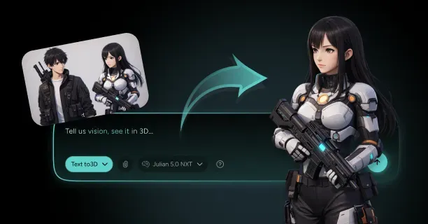
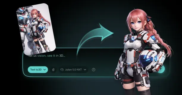
To make robot character 3D models from images, feed a clean orthographic reference into an image-to-3D generator, then treat the result as a kit of parts rather than a single sculpt: separate the mesh at every joint, rebuild crisp panel lines and hard edges, and texture with a metallic PBR set. A robot 3d model maker like Threedium runs the reconstruction half with its Julian NXT generator, which converts a reference image or a written description into a textured mesh with polygon optimization and export to GLB, USDZ, and FBX. What separates a usable robot from a melted action figure is everything you do after generation: part separation, weighted normals, and a rig built around mechanical pivots instead of human anatomy.
Machines are the hardest character to fake. An organic creature forgives a soft edge because skin is soft. A mech does not: the eye reads a 2 mm bevel as machined metal and a 15 mm rounded blob as plastic, and no texturing rescues the second. Hence the weight this page puts on hard surface modeling hygiene and rigid rigging.
Before you generate anything, decide whether the robot needs to move. A static hero prop for a render and an articulated game character are two different meshes, and converting the first into the second costs more time than starting over with separation planned in.
Choose Your Robot Reference: Concept Art, Toy Photos, or AI Turnarounds
Three input types dominate robot character design work, and they fail in different ways. Flat concept art gives you the cleanest silhouette and the most control over proportion, but it usually shows a single three-quarter view with painted-in ambient occlusion that the generator can mistake for geometry. Photographs of physical toys and model kits are the most reliable single source because a real object has real parallax, honest specular response, and visible seam lines that map directly onto part boundaries. AI-generated turnarounds are fast and free, but they drift: the shoulder vents in the front view will not match the back view, and the generator will average the difference into mush.
If you can only supply one image, supply a straight-on front view of a toy or kit under flat light. If you can supply three, use front, side, and back at the same camera height and the same focal length. Mixing a 24 mm wide-angle front shot with a 100 mm side shot guarantees a torso that is too deep and a head that is too large, and that error compounds when the model is later scaled to a character rig.
- Shoot or source at 2048 px minimum on the long edge. Panel detail below that resolution simply does not survive reconstruction.
- Avoid heavy rim lighting and lens bloom. Blown highlights on chrome read as missing geometry and produce craters.
- Prefer matte or satin surfaces over mirror chrome. If your reference is polished, dust it lightly or shoot it through a diffuser.
- Include a scale cue, such as a cockpit hatch or a human figure, so you can set real-world units later without guessing.
- Keep the pose neutral. A dynamic action pose bakes rotation into the mesh and makes rigging significantly harder.
Prepare the Image: Orthographic Views and Clean Silhouettes for Hard-Surface Conversion
Reconstruction quality is decided in your image editor, not in the generator. The goal is an isolated silhouette on a flat background with no cast shadow touching the figure. Cut the robot out on its own layer, fill the background with a neutral mid-grey around RGB 128,128,128, and remove any contact shadow, reflection, or ground plane. Environment pixels that touch the silhouette get pulled into the mesh as fins and skirts, and on a machine those artefacts are far more visible than on a furred creature because the eye expects straight lines.
For an image to 3d robot conversion using multiple views, align them on a shared canvas so that the ankle line, hip line, shoulder line, and top of the head sit at identical pixel heights across every view. Ten pixels of vertical drift between front and side is enough to skew the whole torso. If your reference is a rendered turntable, re-render it with an orthographic camera; perspective turnarounds converge toward the vanishing point and the generator interprets that taper as a real change in width.
Write a Robot Prompt That Defines Body Type, Materials, and Part Separation
Whether you are running text-to-3D or supplementing an image with a description, an ai robot generator responds to structural nouns far better than to adjectives. "Cool futuristic battle robot" produces a generic humanoid with smooth pauldrons. "Bipedal industrial mech, 4 m tall, boxy chest block with hinged front hatch, cylindrical shoulder pods, reverse-joint digitigrade legs, exposed piston on each knee, brushed steel armour over dark grey inner frame" produces something you can actually build on.
Structure the prompt in four passes. First the archetype and scale. Second the body plan, joint by joint, naming the shape primitive for each major volume: block, cylinder, wedge, sphere. Third the material split, separating outer armour from inner frame, since that split will become your material slots. Fourth the surface language: panel density, vent placement, decal presence, and whether the finish is factory-fresh or weathered.
- Name explicit part boundaries: "separate forearm, elbow hinge, and upper arm" tells the generator where the mesh should break.
- Give real dimensions. "2.2 m tall" and "0.4 m shoulder width" anchor proportion better than "large".
- Specify material by name and finish: "anodized aluminium, satin, roughness 0.35" beats "shiny metal".
- Call out the emissive elements separately: "cyan sensor visor, three amber status lights on chest".
- Exclude what you do not want: "no cape, no organic musculature, no rounded shoulders".
Generate the Base Mesh With Threedium's Image-to-3D Pipeline
With the reference prepared and the prompt written, run generation. Threedium's 3D model generation pipeline returns a textured mesh with a PBR material set, an automatic UV layout, and polygon optimization already applied, typically in the low tens of thousands of triangles for a full character body. Treat that first result as a blockout, not a deliverable. Its job is to lock proportion, silhouette, and volume relationships so that every hour you spend afterward is spent on detail rather than on establishing where the knee goes.
Generate three to five variants before you pick one. Reconstruction is stochastic: one pass may resolve the shoulder pod as a clean cylinder and another may fuse it into the chest. Judge candidates on structure only, textures hidden, in flat grey matcap. Is the silhouette right, are the major volumes separable, is the joint area open enough to rotate.
Enterprise tiers on the platform add refinement by human 3D artists, which is worth costing out when the model is a hero asset. The economics are simple: an artist pass on a generated base is far cheaper than a from-scratch commission, because the expensive part, establishing form and proportion from reference, is already done. For background robots, crowd units, or a fleet of twenty drone variants, the raw generation plus your own cleanup is usually sufficient.
Check Part Separation: Why a Robot Should Never Be One Welded Mesh
Generated meshes arrive as one continuous watertight surface, which is correct for an organic character and fatal for a robot: a welded shoulder cannot rotate without stretching the armour like rubber. This is the check most people skip and the one that decides whether the model can move at all.
Open the mesh and separate it into discrete objects along every mechanical boundary. A humanoid robot typically decomposes into 18 to 30 rigid parts: cranium, jaw or faceplate, neck column, upper chest, lower torso, pelvis, two shoulder pods, two upper arms, two elbow housings, two forearms, two hands, two hip joints, two thighs, two knee housings, two shins, two feet. Add thruster packs, hatches, and weapon mounts on top of that. Each part becomes its own object with its own origin placed at its rotation pivot.
Where the generator has fused two parts, cut the mesh with a knife project or boolean plane along the intended seam and cap the opening with a flat n-gon that will never be seen. If the fused region is badly formed, delete it and replace it with a primitive cylinder joint, which is usually what should have been there.
Cap every cut you make. An open shell will render fine in the viewport and then produce a black hole in a game engine the moment backface culling is on, or a non-manifold error the moment you try to 3D print it.
Refine Panel Lines, Vents, and Greebles Without Muddying the Silhouette
Surface detail works in three tiers, and mixing them is what makes amateur mechs look noisy. Tier one is primary form, the big volumes that read at 100 px. Tier two is panel division. Tier three is greebles: bolts, grilles, hydraulic lines, and clutter that only read close up. Build in that order and never let tier three compensate for a weak tier one.
Panel lines should follow structural logic. Real armour panels are bounded by where they need to be removed for maintenance, where the frame underneath changes direction, and where a joint requires clearance. Run them across the chest in asymmetric divisions rather than symmetric ones, break long panels with a short perpendicular seam, and avoid running a line straight through the exact centre of a face. On the mesh, cut panel lines as a shallow inset of 1 to 3 mm at real-world scale, or bake them from a high-poly source into a normal map if your polygon budget is tight.
Vents and grilles are best handled as texture plus a simple geometric frame, since a normal map with an alpha-cut plane delivers forty louvres for a fraction of the triangles. Reserve modelled vents for silhouette-breaking intakes the camera gets close to.
- Keep greeble density uneven. Cluster detail around joints, intakes, and hatches, and leave large armour faces deliberately empty as visual rest.
- Do not place greebles across a joint gap. Anything spanning two parts will tear the first time the joint rotates.
- Match greeble scale to the robot's scale. Bolts sized for a 2 m android on a 12 m mech make it look like a toy.
- Test at final camera distance constantly. Detail you cannot see is polygon budget you cannot spend elsewhere.
Kitbashing Greeble Libraries Onto a Generated Base Without Exploding the Polycount
Kitbashing is the fastest route from a clean generated blockout to a convincing machine, and it is also the fastest route to a 4-million-triangle model that no engine will load. The discipline is to keep the kitbash layer entirely separate from the shipping mesh. Build a duplicate of your generated base, scatter library parts across it freely, and treat that assembly purely as a bake source. The version you export is the low-poly base with the kitbash detail transferred into normal and ambient occlusion maps.
Organize a personal greeble library by function: connectors, hinges, vents, hydraulics, fasteners, cable clamps, warning plates. When placing them, snap to the surface normal, sink each greeble slightly into the host surface, and rotate every instance a few degrees off axis so repetition does not read as a pattern.
Budget discipline matters. A single library hinge can carry 8,000 triangles because it was authored for a hero render, and forty of them puts you 320,000 triangles over budget on detail that occupies 2 percent of screen space. Before baking, decimate each library part to the lowest density that still holds its bevels, and use linked instances rather than duplicates so the scene stays workable.
Bake the assembly onto the separated low-poly parts with a cage offset large enough to catch protruding greebles, usually 2 to 5 mm at model scale, and bake problem parts individually rather than fighting the cage across the whole body.
Retopologize Hard Surfaces: Keeping Crisp Edges With Weighted Normals
Retopology for hard surface modeling is far simpler than for organics because robot parts are rigid: you do not need edge loops flowing around a shoulder, you need flat faces with clean boundaries and consistent quad density on curved sections.
The crucial technique is weighted normals. Instead of adding a three-segment support loop next to every hard edge to keep a subdivision or shading break clean, apply a weighted normal modifier or the equivalent custom normal operation. It biases vertex normals toward the largest adjacent face, so a single bevel of one or two segments shades like a much denser mesh. On a typical robot this cuts triangle count by 30 to 50 percent compared with a support-loop approach at identical visual quality.
Pair weighted normals with a uniform bevel of 0.5 to 2 mm at real-world scale on every hard edge. Perfectly sharp corners do not exist on manufactured objects and catch no specular highlight, which is why an unbevelled model looks like untextured CAD.
| Robot class | Target triangles | Texture set | Typical use |
|---|---|---|---|
| Mobile or web AR drone | 8,000 - 20,000 | 1 x 1024 or 2048 | USDZ product viewers, mobile games |
| Background or crowd unit | 15,000 - 35,000 | 1 x 2048 | Swarm enemies, set dressing |
| Playable game-ready robot | 40,000 - 90,000 | 2 x 2048 or 1 x 4096 | Player character, named enemy |
| Hero mech, cinematic | 150,000 - 500,000 | 3 - 6 x 4096 | Close-up cutscenes, key art |
| Offline film or print master | 1M+ or subdivision | UDIM sets | Rendered film, high-res 3D print |
UV Unwrap Mechanical Parts With Seams Hidden Along Panel Gaps
Robots are the easiest characters to unwrap and the easiest to unwrap badly. Easy because every seam has an obvious hiding place: the panel gap. Badly because generated auto-UVs chop the mesh into hundreds of tiny islands with no consistent orientation, which destroys any hope of applying a directional material like brushed metal or a decal sheet.
Re-unwrap by hand or with a guided algorithm, placing seams exactly along the recessed panel lines you cut earlier and along the boundaries where parts meet. Because those edges are already visually broken, a texture discontinuity there is invisible. Then orient every island so that the up direction of the part matches the up direction in UV space. This costs a few minutes and pays off the first time you apply an anisotropic brushed finish or a straight decal stripe.
- Keep texel density uniform across the body, typically 512 to 1024 pixels per metre for a game-ready robot. Mismatched density is instantly visible on flat armour.
- Mirror symmetrical parts by stacking UV islands to double effective resolution, then break the mirror only for asymmetric decals, which get their own small island or a separate decal layer.
- Pack at a 2 to 8 px margin at your target resolution to prevent mip-map bleed between islands.
- Group by material, not by body part. All matte armour on one set, all inner frame and hydraulics on another, all emissive elements on a third.
Texture With PBR: Metallic, Roughness, Normal, and Decal Passes
Machined surfaces live or die on the metallic and roughness channels. Metallic is close to binary: painted armour, plastic, rubber, and ceramic sit at 0.0, and bare steel, aluminium, titanium, and chrome sit at 1.0. Intermediate values are almost always a mistake, with the exception of a narrow transition band where paint has worn through to metal. If your robot looks like grey plastic no matter how you light it, the cause is nearly always a metallic map sitting at 0.5 across the whole body.
Roughness carries material identity and should never be a flat value. A useful starting set is 0.15 to 0.25 for polished chrome trim, 0.3 to 0.45 for satin anodized armour, 0.5 to 0.7 for matte industrial paint, and 0.8 plus for cast or sandblasted frame components. Layer subtle noise over each so the highlight breaks up instead of sitting as a clean band.
Normal maps carry the detail you did not model: rivets, fine grilles, stamped ribs, machining swirl. Bake from the kitbashed high-poly assembly, then check for two faults. First, seam mismatches where the tangent basis differs across a UV island boundary, visible as a hairline crease. Second, a normal map fighting the weighted normals you applied earlier, which shows as a dark band along bevels. Handle decals, serial numbers, and hazard stripes as a separate pass rather than painting them into the base albedo, so one texture swap re-skins the same robot into a dozen factions.
Add Wear: Edge Chipping, Oil Stains, and Scorch Marks on Armor Plating
Wear is what converts a clean asset into a machine with a history, and it follows physics rather than taste. Damage concentrates where contact happens: leading edges, corners, the outer face of forearms and shins, around hatches that are opened repeatedly, and along the underside of feet. A curvature or convexity mask drives most of this automatically, and it should be masked further so the wear is not perfectly even across every edge.
Edge chipping on painted armour is a two-layer effect. The top layer removes paint to expose bare metal: metallic goes to 1.0 and roughness drops. The second layer, at larger scale and lower opacity, is scuffed paint around the chip where the finish is abraded but not removed. Skipping it is why quick weathering jobs look like stickers.
- Oil and hydraulic staining runs downward from joints and seals under gravity. Darken albedo, drop roughness sharply to 0.1 to 0.2, and leave metallic unchanged since a fluid film is a dielectric coating.
- Dust and dry grime collect in upward-facing cavities and recesses. Drive with an ambient occlusion plus world-space-up mask, raise roughness toward 0.85, and desaturate.
- Scorch marks are soot, not burnt paint: near-black albedo, high roughness, and a soft radial falloff from the impact point. Add a small crater in the normal map at the centre.
- Rust belongs only on iron alloys. Do not rust an aluminium or composite panel, and keep rust bleeding downward from fasteners rather than blooming randomly.
Weather at the end, on a duplicate material stack. A battle-damaged variant and a factory-fresh variant of the same robot should share one mesh and one UV layout, with only the texture set swapped. Baking damage into geometry locks you out of that reuse.
Set Up Emissive Maps for Eyes, Core Reactors, and Status Lights
An emissive texture is the cheapest characterization tool a robot has. A visor that glows amber reads as industrial, cyan as clinical, and red as hostile, and the change costs one texture swap. Author emission as its own greyscale or colour map with hard-edged shapes: on a machine, the light comes from a bounded lens, panel, or strip, not from a soft glow across the armour. Any softness should come from bloom in the renderer, not from a blurred emissive map.
Keep emissive geometry on a dedicated material slot so the engine can treat it separately for bloom, so you can animate intensity without touching the armour shader, and so damaged states with dead status lights are one texture away. In glTF and GLB, emission rides on the emissive texture and factor, with an emissive strength extension covering values above 1.0.
Push strength rather than saturation. Status lights sit low, around 1.0 to 2.0 in linear terms; a core reactor or thruster runs 5.0 to 20.0 so it blows out and casts bloom. Pair each zone with a small point light, since emissive materials alone do not illuminate surrounding armour in most real-time renderers, and a glowing chest that fails to light the chin looks pasted on.
Animation is where emission earns its keep. A slow sine pulse at roughly 0.4 to 0.8 Hz reads as an idle heartbeat, a rapid stutter reads as damage, and a scrolling UV offset across a light strip reads as data flow. All three are two-line shader graphs.
Export a Game-Ready GLB, FBX, or USDZ With Separate Material Slots
Export format follows destination. GLB is the default for web, WebXR, and any glTF-native viewer, and it packs geometry, textures, materials, and animation into one binary file. FBX remains the safest interchange into Unity, Unreal, Maya, and 3ds Max, especially when a complex skeleton and multiple animation takes are involved. USDZ is what Apple's AR Quick Look consumes, so it is the format for an iOS AR placement of your robot. Threedium exports all three, which means you can generate once and deliver to every target without re-authoring.
Whatever the format, preserve material slots. A robot collapsed into one material cannot have its armour re-skinned, its emission animated, or its frame reshaded. Three to five slots is the sweet spot: outer armour, inner frame, emissive, and optionally glass and rubber. Keep names consistent across your fleet so engine-side overrides can be scripted.
- Apply all transforms and set scale to 1.0 before export. Unapplied scale is the leading cause of a rig that behaves correctly in the DCC and explodes in the engine.
- Confirm the up axis. glTF and GLB are Y-up, FBX for Unreal wants Z-up, and a mismatch lands your mech on its back.
- Freeze part origins where you want them: at the rotation pivot for rigged parts, at the world origin for parts driven purely by bones.
- Triangulate before export rather than letting the exporter do it, so you control how n-gons on capped cuts are split.
- Test the export in a neutral viewer before handing it off. Anything that looks wrong there will look wrong everywhere.
For anything shipping into a real-time engine, run the file against a game-ready checklist: triangle count inside budget, texture resolutions power-of-two, no unused UV channels, no duplicate materials, skeleton hierarchy clean, and the model sitting at the world origin with its feet on the ground plane.
How Do You Rig a Robot 3D Model So Its Joints Actually Articulate?
You rig a robot by treating it as a kinematic assembly rather than a skinned body: place bones at real mechanical pivots, assign each rigid part to a single bone at 100 percent weight, build clearance gaps into the geometry so plates never intersect, and constrain rotation to the ranges a real servo could produce. Robot rigging is a different discipline from character skinning, and this section is where most generated robots fall apart. Threedium's automatic rigging gets you a working skeleton fast, including facial rigs with 52 ARKit blendshapes where a robot has an expressive face, but the mechanical joint logic below is what makes the result hold up under animation.
The rule that governs everything here: rigid bodies do not deform, they rotate about axes. Every problem in robot rigging reduces to identifying the axis, placing the pivot on it, and limiting travel around it.
Plan Joint Types Before Rigging: Hinges, Ball Joints, Swivels, and Pistons
Before you place a single bone, walk the model and label every joint with its mechanical type. Four types cover almost everything. A hinge has one rotational axis, like an elbow or knee. A ball joint has three, like a hip or a shoulder socket. A swivel rotates about the limb's own long axis, like a wrist roll or a waist twist. A piston or linear actuator translates rather than rotates and drives a hinge from the side.
Labelling matters because the geometry has to agree with the label. A hinge needs a visible cylindrical housing whose axis coincides exactly with the bone's rotation axis, otherwise the forearm will visibly orbit rather than pivot. A ball joint needs a spherical volume large enough that the socket lip never exposes an interior gap at full extension. A swivel needs a ring or collar so the eye has a reason for the two halves to rotate relative to each other.
| Joint type | Degrees of freedom | Geometry required | Rig solution |
|---|---|---|---|
| Hinge (elbow, knee) | 1 rotational | Cylindrical housing, axis aligned | Single bone, two axes locked |
| Ball (hip, shoulder) | 3 rotational | Sphere in socket with lip coverage | Single bone, cone limit |
| Swivel (wrist, waist) | 1 rotational, along limb axis | Collar or ring, split geometry | Dedicated roll bone |
| Piston or actuator | 1 translational | Rod plus cylinder, telescoping | Two bones, aim constraints |
| Universal or double hinge | 2 rotational | Cross-block between yokes | Two stacked single-axis bones |
Write the joint list down before rigging. A humanoid mech 3d model typically carries 12 to 20 labelled joints, and enumerating them turns a fuzzy problem into a checklist.
Design Clearance Gaps So Armor Panels Never Clip Mid-Animation
Clipping is the defining failure of robot animation, and it is a modelling problem disguised as a rigging problem: when two rigid plates meet, rotation past a certain angle drives one through the other, and no skinning trick fixes it. Build clearance into the geometry before you animate.
Give every joint a physical gap of 2 to 5 mm at real-world scale, scaled proportionally to 20 to 50 mm on a 12 m mech. Then chamfer the facing edges of each plate so that as the joint closes the chamfers meet flush rather than one corner spearing the neighbouring surface. Real hardware does exactly this, which is why chamfered clearance reads as authentic rather than as a gap.
Wide-range joints need a sliding or nested solution: a telescoping sleeve, overlapping plates that slide across each other like lamellar armour, or a floating pauldron on its own bone. The floating pauldron is the workhorse: constrain it to copy roughly 40 to 60 percent of the upper arm's rotation and the shoulder stays covered through a full raise without intersecting the chest.
Test clearance at the extremes, not at rest. Pose the arm fully overhead, the elbow fully closed, the knee at maximum crouch, and the waist at full twist. If nothing clips in those four poses, ordinary animation will be safe.
Rigid Skinning vs Weight Painting: Why Robot Parts Take 100% Bone Weights
Organic characters use smooth skinning, where a vertex near the elbow is influenced by both the upper arm and forearm bones so the surface bends. Applying that to a robot produces armour that visibly stretches and pinches, which destroys the illusion of solid metal in a single frame. Every vertex of a rigid part must be weighted 100 percent to exactly one bone, with zero influence from any other.
Skip weight painting entirely. Because the mesh is already separated, assign each part wholesale: select the object or vertex group, assign weight 1.0 to its bone, move on. Then run a limit-total operation set to one influence per vertex to strip any stray secondary weights the auto-binder introduced. Twenty parts take about ten minutes.
Automatic rigging tools bind with smooth falloff by default, so always audit the result. Rotate a joint to 90 degrees and look at the seam: if the parts stay rigid and simply rotate past each other, the weights are correct. Any bulge, taper, or rubbery transition means multi-bone influence remains.
The exception is any genuinely soft component: rubber gaskets, fabric cabling, or the synthetic skin on an android 3d model where flesh meets frame. Those want smooth weights, on separate objects, so soft-body skinning never contaminates the rigid armour beside it.
Place Bones at Mechanical Pivots, Not Human Anatomy Landmarks
Every rigging tutorial teaches you to place the knee bone at the anatomical knee, roughly at the centre of the joint mass. On a robot, that is wrong. The bone must sit exactly on the axis of the physical hinge you modelled, which is often several centimetres forward, back, or above where a human joint would be. Reverse-joint mech legs place the knee axis behind the leg entirely. Get this wrong and the shin will swing through an arc that does not match its own hinge housing, and the whole limb will look like it is floating.
The procedure is geometric, not eyeballed. Snap the 3D cursor to the centre of the cylindrical housing, using the circle of vertices at its end cap as reference, and place the joint head there. Align the bone's roll so one local axis is parallel to the cylinder's axis, lock the other two, and rotation about that bone becomes physically identical to the real hinge.
- Snap pivots to geometry, never by eye. A 3 mm offset on an elbow is visible the moment the arm bends past 60 degrees.
- Add dedicated roll bones for forearm and shin twist rather than twisting the parent hinge bone, which would rotate the hinge housing itself.
- Keep the hierarchy strictly parent to child down each limb, with the pelvis or chest as root, so IK solvers behave predictably.
- Name bones with a consistent convention and a side suffix so retargeting tools and engine-side scripts can find them.
- Zero out and apply rest pose transforms before you start animating, so the bind pose is the identity.
Rig Pistons and Hydraulics With Aim Constraints and Stretch Bones
Pistons are the detail that most convincingly sells a machine in motion, and they are trivially cheap to rig correctly. A piston is two parts: a cylinder anchored at one end and a rod anchored at the other, sliding inside it. Rigged properly, the pair automatically extends and contracts as the joint they span rotates, with no keyframes at all.
Build it with two bones. Bone A sits at the cylinder's anchor and is parented to the upper limb. Bone B sits at the rod's anchor and is parented to the lower limb. Give bone A an aim or damped-track constraint targeting bone B, and give bone B the reverse. Now both halves always point at each other regardless of joint angle. Assign the cylinder mesh rigidly to bone A and the rod mesh to bone B, and the piston is done.
For the sliding motion itself you have two options. The simpler is to let each half stay rigid and rely on the rod being long enough to remain sheathed at all angles, which works when travel is short. The better one is a stretch-to constraint on bone A so it scales along its length toward bone B, with the mesh assigned so the cylinder body stretches while its end caps do not. Cap the stretch factor at roughly 0.7 to 1.4 of rest length so the piston never inverts or telescopes past its housing at extreme poses.
Set Rotation Limits That Mimic Real Servo and Actuator Ranges
An unlimited rig lets an animator hyperextend an elbow backwards or spin a head 360 degrees, and the resulting frame reads as broken rather than expressive. Rotation limits are both a realism tool and a productivity tool: they let an animator pose fast without checking every axis, because the rig physically cannot enter an impossible state.
Apply limit-rotation constraints in local space to every joint, locking the axes that the mechanical type does not permit and bounding the one or three that it does. Reasonable defaults for a humanoid robot are listed below; adjust to the specific machine, since a heavily armoured mech will have far less shoulder travel than a slim android.
| Joint | Primary axis range | Secondary | Notes |
|---|---|---|---|
| Elbow hinge | 0 to 145 degrees | Locked | Never allow negative, no hyperextension |
| Knee hinge | 0 to 130 degrees | Locked | Reverse-joint legs invert the sign |
| Shoulder ball | -60 to 170 pitch | -45 to 110 yaw | Clamp with a cone, not per-axis boxes |
| Hip ball | -30 to 110 pitch | -45 to 45 yaw | Armour skirt usually limits this further |
| Neck or head yaw | -90 to 90 degrees | -30 to 30 pitch | Cable routing forbids full rotation |
| Waist swivel | -45 to 45 degrees | Locked | Split across two bones for a smoother twist |
| Ankle | -25 to 40 pitch | -15 to 15 roll | Add a toe hinge for a proper foot roll |
Set limits after testing clearance, not before. If the shoulder plate clips the chest at 115 degrees of raise, the limit is 110 degrees, whatever a real servo could do: the limit encodes what the geometry can survive.
Drive Cables, Hoses, and Antennae With Spline IK and Jiggle Bones
Cables and hoses are the counterweight to all that rigidity. A robot of pure hard plate moves like a stack of boxes; one bundle of flexing conduit across the shoulder makes the same animation feel alive.
Rig each cable with a chain of 5 to 12 bones driven by spline IK along a curve, with the curve's endpoints hooked to the two parts the cable connects. As the joint moves, the curve deforms, the bone chain follows, and the cable bends naturally. Unlike the armour, a cable does want smooth skinning, so weight it with a normal falloff across the chain. Keep the bone count modest: 8 bones on a 40 cm hose is smooth enough, and 30 is just skinning cost.
Antennae, whip aerials, and loose cable ends want secondary motion instead. A jiggle or dynamic bone setup with stiffness around 0.4 to 0.6 and light damping gives a lag-and-settle that sells mass. Tune it on a fast head turn: the antenna should trail two or three frames and settle within half a second.
- Give every cable slack at rest. A cable rigged taut has nowhere to go and will stretch visibly the moment the joint opens.
- Route cables away from the outside of joints where they would be crushed. Real hardware routes them along the inner face for exactly this reason.
- Confirm your export target supports dynamic bones. Many engines require a runtime component, so bake a baseline motion into the animation clip as a fallback.
- Cap total bone count. Cables and jiggle chains can quietly double a skeleton, which matters on mobile and in crowd scenarios.
Retarget Humanoid Mocap Onto Non-Human Robot Skeletons
Motion capture libraries are recorded on human bodies, and most robots are not human-proportioned. Retargeting a standard walk onto a mech with a doubled torso ratio and reverse-joint legs produces sliding feet, a floating pelvis, and knees that bend the wrong way.
Where the robot has a recognizable hips, spine, chest, neck, head, two arms, two legs layout, map those bones to the engine's humanoid rig and set source and target to the same T-pose first, since a mismatched reference pose causes most retarget rotation offsets. For genuinely non-human topology, the workflow changes from retargeting to motion transfer plus IK correction. Retarget only the upper body, which is usually close enough to human, and drive the legs procedurally with a two-bone or three-bone IK solver whose foot targets follow the mocap footfall timing. This gives you human-like timing and weight shift with mechanically correct leg motion. Reverse-joint legs specifically need the pole vector flipped and the knee limit sign inverted, or the solver will fight itself every frame.
Always correct foot sliding afterward: lock the planted foot to a world position for its contact duration and let the root translate to compensate. On a heavy mech, exaggerate ground contact with a one or two frame settle after each footfall and a small vertical dip in the root, and a generic human walk starts to read as several tons of machine. Threedium's character model pipeline exports a clean named hierarchy, which makes the initial bone mapping step much faster.
Stress-Test Articulation With Walk Cycles and Extreme Poses Before Export
Never ship a rig that has only been seen in bind pose. Robot rigs fail in specific, findable ways, and twenty minutes of deliberate abuse catches almost all of them before an animator wastes a day on a broken asset.
Run a fixed test sequence on every robot you build. Pose it through a full crouch with knees maximally closed, arms fully overhead, both elbows fully flexed, waist at full twist in both directions, and head at maximum yaw and pitch. Then play a generic walk cycle, a run, and an idle, watching from front, side, and a low three-quarter angle. Watch specifically the shoulder to chest intersection, the hip to skirt intersection, the knee housing interior, and every piston.
- Turn on backface culling during the test. Interior faces that show through a joint gap are invisible with culling off and glaring with it on.
- Check the joint interiors are actually filled. A hinge that reveals an empty shell at 90 degrees needs an inner cylinder, not a smaller rotation limit.
- Verify part origins have not drifted. A part whose origin sits at world zero instead of its pivot will swing wildly and is easy to miss in bind pose.
- Confirm the model exports and re-imports with the rig intact. Round-trip through your target format before declaring the asset finished.
- Test at engine scale with real lighting. Clipping that hides in a grey viewport becomes obvious under a hard key light.
Which Robot Styles Can You Generate: Mechs, Androids, or Drones?
All three, plus quadrupeds, retro tin toys, and industrial arms. What changes between them is proportion, joint plan, and surface language, and each of those is steerable through the reference image and prompt. The practical differences are large enough that it pays to decide the archetype before generating rather than trying to convert a humanoid android into a heavy mech afterward.
Mech Proportions: Heavy Torso, Reverse-Joint Legs, and Cockpit Scale
A mech reads as massive because of ratio, not size. The defining move is a torso that is disproportionately large relative to the head and limbs: where a human head is roughly one seventh of total height, a mech head is typically one twelfth to one twentieth, and often smaller. Shoulders sit wide, frequently exceeding hip width by 1.4 to 1.8 times, and the chest block projects forward to imply armour depth and internal volume.
Legs carry the second half of the read. Reverse-joint or digitigrade legs, where the visible knee bends backward, immediately signal a machine rather than a man in a suit, and they solve a real engineering problem by putting the actuator behind the load line. Feet must be large: a mech foot is proportionally two to three times a human foot relative to leg length, because the eye needs to believe the thing will not topple. Ground contact area is the single most effective cue for weight.
Scale cues make the size legible: a cockpit hatch sized for a human, a boarding ladder, handholds, warning stencils readable from the ground. Without them, a 15 m mech 3d model renders identically to a 2 m one, so include a scale reference in both the prompt and the reference image.
Android Proportions: Blending Synthetic Anatomy With Armor Plating
An android 3d model is the hardest robot to make convincing because it sits directly in the uncanny valley by design. It has to read as humanoid enough to be relatable and mechanical enough to be clearly not human. The successful approach is to keep human proportion almost exactly, roughly seven and a half heads tall with correct limb ratios, and then break it with material and seam logic rather than with distorted anatomy.
Design the body as two layers: an inner frame that shows at the joints, the neck, the midriff, and behind the knees, and outer plating that covers the large muscle groups. That inner frame is where you put the mechanical vocabulary, since it can be as complex as you like without disturbing the human silhouette. The plating stays smooth and follows anatomical form, with seams placed where a real garment would have panels: along the outer arm, down the flank, across the collarbone.
Decide the face early. A fully sculpted synthetic face can carry a 52-blendshape ARKit facial rig and support real dialogue, but every millimetre of geometry error registers as wrongness. A visored face sidesteps that and gains an emissive texture as its expressive channel, which is far easier to make convincing than a near-human face at 80 percent fidelity.
Drones, Quadrupeds, and Other Non-Humanoid Robot Bodies
Non-humanoid robots are the easiest category to generate well and the easiest to rig, because they carry fewer joints and no anatomical expectations. A quadcopter drone is a central body, four arms, four rotors, a sensor gimbal, and landing skids: perhaps eight moving parts total, most of which spin about a single fixed axis. Rotors do not even need bones if the engine can rotate a transform directly.
Quadrupeds animate with real personality while staying mechanically simple: four identical leg assemblies, each a hip yaw, hip pitch, knee, and ankle driven by a two-bone or three-bone IK chain with a foot target. Build one leg, mirror and duplicate, and the rig is done in a fraction of the time a humanoid takes. Keep the centre of mass low and offset the gait so diagonal pairs move together for a trot.
- Sensor gimbals want two or three nested bones for pan, tilt, and roll, parented in that order, so the camera can track a target independently of the body.
- Spinning parts, rotors, tracks, and turbines, should be their own objects with origins exactly on the spin axis so a constant rotation driver just works.
- Wheeled and tracked bases need a suspension rig: each wheel on its own bone with a limited vertical travel of a few centimetres, driven by ground raycasts in-engine.
- Snake, tentacle, and worm bodies use a single spline IK chain of 15 to 30 bones with overlapping segment plates that slide across each other.
Retro Tin Toy vs Military Hard-Surface: Steering Style Through Prompts
Style is largely a function of three variables: surface curvature, panel density, and colour treatment. Retro tin toy robots use high curvature and low panel density: rounded box torsos, simple cylindrical limbs, minimal seams, and detail supplied by printed lithography rather than geometry. Military hard surface inverts all three: flat faces with tight chamfers, heavy panel division, and detail carried entirely by modelled and normal-mapped geometry.
Steer this through prompt vocabulary. For retro, use words like stamped tin, rounded box torso, wind-up key, printed dial face, riveted seams, saturated primary colours, litho decal, and a limited palette of red, blue, and cream. For military, use words like faceted armour, ballistic plating, chamfered edges, modular ammunition box, matte olive drab, stencilled unit numbers, and machined fasteners. The words in the prompt map directly onto surface treatment in the result.
Factory-Fresh vs Battle-Damaged Finishes and When Each Reads Better
Finish is a storytelling decision before a technical one. Factory-fresh reads as new, clinical, or unproven. Battle-damaged reads as veteran, used, or barely holding together. Choosing by default rather than by intent is why so many portfolio mechs wear scratches that say nothing.
Factory-fresh is technically harder, which surprises people. Weathering hides errors: a chipped panel forgives a UV seam, an uneven bake, and a slightly wrong bevel. A pristine surface hides nothing, so add value with subtle manufacturing detail: faint machining swirl, clear-coat orange peel, fingerprint smudges near handles, and a slight roughness gradient where dust would first settle.
Battle-damaged rewards restraint and physical logic. Damage should be directional: if the robot took fire from the front left, scorch and impact should cluster there and taper away, not scatter evenly. Layer in a sequence: base finish, then general grime, then handling wear on edges, then fluid staining from joints, then combat damage last and sparingly. A model where roughly 15 to 25 percent of the surface shows meaningful wear reads as a veteran machine. Push past half and it reads as scrap.
3D-Printable Robots With Print-in-Place Articulated Joints
A generated robot base can be prepared for 3D printing, and the modular part separation you already did is most of the work: printing individual parts and assembling them with pins or magnets is usually cleaner than attempting a single-piece print. Convert each part to a watertight solid, thicken anything under 1.5 mm for FDM or 0.8 mm for resin, and scale the assembly to your target size before checking wall thickness, since thickness is absolute rather than relative.
Print-in-place articulation, where hinges and ball joints print pre-assembled with a small clearance gap of around 0.2 to 0.4 mm so they move straight off the plate, is a specialized discipline with its own tolerance rules. Orient each joint so the moving surfaces sit parallel to the build plate, keep supports out of the gap, and tune clearance per printer and per material: PLA at 0.3 mm often frees cleanly where PETG at the same gap welds shut. Modular pinned assembly stays the safer route for a detailed mech 3d model, since it lets you print armour panels flat for surface quality and still keep every joint articulated.
Frequently Asked Questions About Robot 3D Model Makers
What is the best AI robot 3D model generator?
The best ai robot generator for you depends on whether you need a rigged, engine-ready asset or a static mesh you will finish yourself. Threedium covers the full path from a reference image or prompt through to a textured, optimized, rigged model exported as GLB, USDZ, or FBX, with human artist refinement available on enterprise tiers. Other tools in the space, including Meshy, Tripo, and Luma, produce good reconstruction meshes but generally leave rigging, part separation, and engine preparation to you.
Evaluate any generator on four criteria specific to machines rather than on generic mesh quality. Does it preserve hard edges instead of rounding them, does it output separable parts or one welded shell, does it produce a metallic-roughness PBR set rather than a baked albedo, and can it export with material slots intact. A tool that scores well on organic creatures can score badly on all four.
Can I turn a drawing of a robot into a 3D model?
Yes. A drawing is a perfectly good input for an image to 3d robot conversion, and in some ways better than a photograph because a clean line drawing has an unambiguous silhouette with no lighting to misinterpret. Upload the drawing, describe any structure the drawing does not show, and the generator reconstructs volume from the outline and internal line work.
The limiting factor is what a single drawing does not contain. A front view says nothing about how deep the chest is or what the back looks like, so the generator infers it, and inference is where designs drift from intent. Supply front, side, and back views aligned to the same height if you have them. Ink your line work at consistent weight, close every contour so there are no gaps in the silhouette, and remove hatching and shading, which the reconstruction can read as geometric depressions.
How much does it cost to commission a custom robot 3D model?
Commissioned robot models typically run from around 150 to 600 USD for a simple untextured drone or prop, 600 to 2,500 USD for a fully textured game-ready humanoid robot, and 3,000 to 15,000 USD or more for a hero mech with a production rig and multiple damage states. Turnaround is usually one to two weeks at the lower end and four to ten weeks for hero work. Rigging is commonly quoted separately at roughly 25 to 40 percent of the modelling fee.
Generation changes that maths. A base mesh takes minutes rather than days, so the question becomes how much finishing the asset needs. For background units, drone swarms, and prototypes, generation plus a few hours of cleanup is the obvious answer. For a hero asset, the hybrid wins: generate the base to lock proportion, then use an artist pass for finishing detail, which lands well below a from-scratch commission because the expensive exploration phase is already resolved.
How do you rig a robot 3D model for animation?
Separate the mesh into rigid parts, place one bone at each mechanical pivot aligned to the real hinge axis, assign each part 100 percent to its single bone with no smooth falloff, apply rotation limits matching the joint type, and add IK chains on the limbs plus aim-constrained bones for pistons. That is the whole method; the difficulty is in doing each step precisely rather than in the concept.
An automatic rigger such as Threedium's rigging service handles skeleton placement and binding, which removes the tedious part. Audit two things afterward: that no vertex has more than one bone influence, and that each joint bone sits on the axis of its housing rather than at the anatomical centre. Fix those two and a rigged robot behaves correctly under any animation you throw at it.
What file format should a robot model use for Unity or Unreal?
Use FBX for both. It is the most reliable carrier for skeletal hierarchies, multiple animation takes, and material slot assignments into Unity and Unreal, and both engines have mature import pipelines for it. GLB works well for Unity via glTF importers and is the right choice for web builds, WebXR, and anything running in a browser. USDZ is for Apple AR Quick Look, not for engine import.
Watch scale and axis on import. Unreal expects centimetres and Z-up, Unity metres and Y-up, and a mismatch gives you a robot either 100 times too large or lying on its back. Apply all transforms, set scale to 1.0, place the model at the world origin with feet on the ground plane, and import textures separately rather than embedded so you control compression per map.
How many polygons should a game-ready robot model have?
For a modern PC or console game, a playable or named robot character sits comfortably at 40,000 to 90,000 triangles. Background and crowd units belong at 15,000 to 35,000, mobile and web AR targets at 8,000 to 20,000, and hero mechs seen in close-up cinematics can justify 150,000 to 500,000. These are per-character budgets, so a scene with twenty robots needs the lower end.
Robots spend their budget differently from organic characters. With no deformation there are no dense joint loops, so polygons go into bevels, panel edges, and silhouette-defining greebles instead. Check your numbers against the game-ready specification for the target platform before committing.
Can I 3D print a robot model with moving joints?
Yes, by two routes. Print-in-place articulation prints the joints pre-assembled with a designed clearance of roughly 0.2 to 0.4 mm between moving surfaces, so the model articulates straight off the build plate. Modular assembly prints parts separately and joins them with printed pins, metal pins, or magnets, which gives stronger and better-tolerance joints and is usually the better choice for a robot you already separated into parts.
Verify before slicing: every part watertight and manifold, no wall thinner than 1.5 mm for FDM or 0.8 mm for resin, and clearance gaps sized for your specific printer's tolerance. Print one test joint before committing to a full 12-hour print; a joint that fuses solid because the gap was 0.1 mm too tight is a lesson best learned on a 20-minute part.